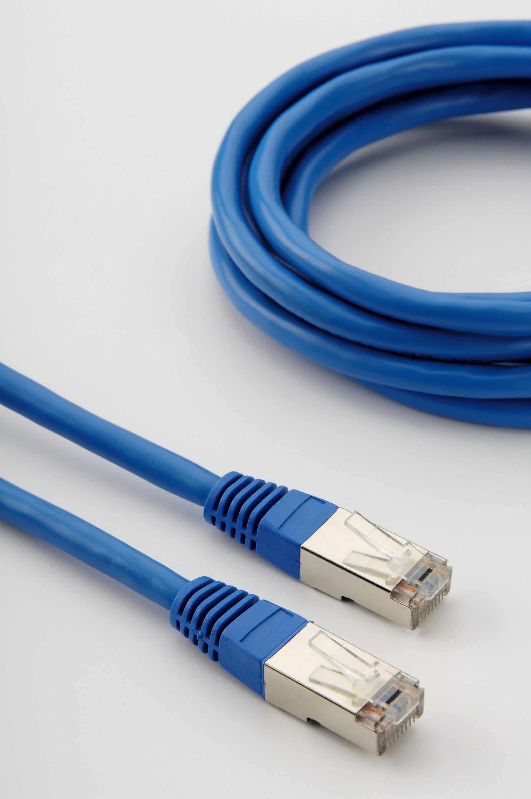
Seven Extra Cool Instruments For Rs485 Cable
본문
Hardware is interfaced to the SPI via three PORTD pins named SCK, MOSI, and MISO brought out to pins 7, 8, and 10 on the Wildcard Port Header (see Appendix B). Slave devices use the master in/slave out pin, MISO, for transmitting, and the master out/slave in pin, MOSI, for receiving data. You can use it to communicate with other devices. We’ll use code from the GETSTART.C program. In fact, the program works the same as it did before, but now it is using the secondary serial port instead of the primary port -- and you didn’t even have to recompile the code! The secondary serial port is connected similarly except that the onboard connection of RTS to CTS, and DSR to DTR are permanent. Although the maximum standard baud rate of the primary serial port is 19200 baud, nonstandard baud rates of over 80 Kbaud can be attained by the 68HC11's on-chip UART and the onboard RS232 driver. The default serial routines used by the onboard kernel assume that full duplex communications are available, so you cannot use the RS485 protocol to program the controller.
The secondary serial port is implemented by a software UART that controls two pins on PortA. We have built sophisticated instruments using the QScreen Controller that operate very reliably using multiple interrupts in addition to the software UART. However, note that the functions that write to EEPROM disable interrupts for 20 msec. The QScreen Controller, however, does not implement hardware handshaking. In some cases, however, a sophisticated network may have device groups on a network that use different clock configurations. For the QScreen, /SS is not used for SPI communication because it is used to control the direction of the RS485 transceiver; you can use any digital I/O line as a /SS signal. Line A voltage, implying A, the green wire, is indeed connected to the driver inverting signal, as seen in a whitepaper. The data exchange format may be a line of ascii text. Transmissions are always initiated by the master device, and consist of an exchange of bytes.
This signal synchronizes the exchange of bytes between the QScreen and its peripherals. Configured as a master device, the QScreen transmits bytes via the "master out/slave in" pin, MOSI. A Modbus RS485 connects a Master device to one or more Slave devices. Henceforth, we shall consider Slave devices to be measuring instruments with serial communication, even if the cabling is similar for all Modbus devices. To ensure that no two devices drive the network at the same time, it is necessary that each slave device be able to disable it’s own RS-485 data transmitter. The shielding may be braided (be formed by a mesh of thin conducting wires) or be a foil (consisting of a sheet of metal wound around the conductors): the two types are equivalent. Anti-inteference layer: Rs485 cables are designed with 2 anti-inteference layers to shield the internal conductors. Function prototypes for this function and other versatile serial I/O routines are defined in the COMM.H header file, and are described in detail in the Control-C Glossary. For example, at 4800 baud (bits per second), each bit lasts about 200 microseconds (µs), and if communications are full duplex (e.g., if the QScreen Controller echoes each incoming character), then there is a serial interrupt every 100 µs or so.
The master and slave can then exchange data. When the exchange is complete, the slave can again execute the Silence() routine to disable its transmitter and begin listening for its name. This section describes the QED-Forth routines that control the RS485 transceiver, and presents some ideas that may prove useful in designing a multi-drop data exchange protocol. Connecting computers together in multi-drop networks is common in factories and laboratories. There are many possible configurations of master/slave networks. RS-485 signals are used in a wide range of computer and automation systems. These characteristics make RS-485 useful in industrial control systems and similar applications. The issue also exists in programmable logic controller applications. If you have not yet compiled the GETSTART program and you want to do the exercises here, open GETSTART.C in your TextPad editor, click on the Make Tool, and after the compilation is done, enter Mosaic Terminal by clicking on the terminal icon and use the "Send File" menu item to send GETSTART.DLF to the QScreen Controller. Because all of the serial I/O routines on the QScreen Controller are revectorable, it is very easy to change the serial port in use without modifying any high level code.
If you adored this write-up and you would such as to receive additional information concerning rs485 cable kindly browse through our webpage.


댓글목록 0
댓글 포인트 안내